FPGA in VHDL - 7-segment display
There is an idea to drive 7-segment display with FPGA
Let's start with the hardware.
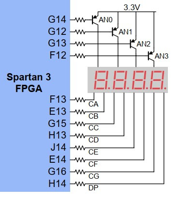
The construction of the display is quite simple. For one display we have 7 + 1 diodes. One LED for each segment of 'figure 8' plus one for display point. See this:


From this schematic you can fetch some important information. To activate a single segment, let's say A, we need to do two things:
1. Drive the anode. As this arrangement is with PNP transistor, the anode is 'activated' by providing LOW state to AnodeDrive. This makes a possibility for the current to flow through transistor.
2. To complete path for current to flow, you need to bring cathode of CA (D1) to the ground (or in our case allow the corresponding pin to be 'LOW' or '0')
Let's see into the Reference manual for Nexys Digital Systems Builder.
How to drive it?

Future project:
To display more digits, we would need employ a concept known as multiplexing, and this work like this: to display number 1234, digit '4' states needs to be given to CA to CG, then Anode 3 has to be activated. This has to be displayed for about 1/10 of a second, then representation of digit '3' has to be forced to CA to CG and Anode 2 to be activated. Again, display this for short time and go to Anode 2 (simultaneously displaying digit '2'), and Anode 1 (displaying 1). Switch these quickly and the user is presented with number 1234. But because of complexity of this, let's work on this in future.
Code concept:
For easy of programming it would be convenient to use a concept of vectors (in VHDL). To define all shapes of digits we will bring 16 shapes. Each will be showing one digit.
Lets see what we observe when want to display digit '2' again. Zeros will be given to segments we want active, remember we use common anode (+). Thus, to allow for current to flow we need to provide zero (LOW, or '0') to particular cathode (- of diode, LED).
Segment to be lit are: ABGED, rest stays dim. So, A-0, B-0, C-1, D-0, E-0, F-1, G-0. What is here then, is '0010010'. (We don't worry abour DP now).
To define 'variable' where VHDL keeps the shapes of digits we will use this:
cathodes : out STD_LOGIC_VECTOR (6 downto 0)
Vector is a group of bits, in this case 7 of them (0 counts as 1st bit, 6 is 7th bit). This brings a simplification when we will define states.
This project needs to have .utc file, where we say what of high-level abstraction (programming part, names - like 'cathodes') is connected. Our concept of cathodes cosist of 7 particular signals, thus we need 7 pins for it. Each will be named cathodes[0] to cathodes[6].
This part of .ucf is:
NET "cathodes[1]" LOC = E13; # B
NET "cathodes[2]" LOC = G15; # C
NET "cathodes[3]" LOC = H13; # D
NET "cathodes[4]" LOC = J14; # E
NET "cathodes[5]" LOC = E14; # F
NET "cathodes[6]" LOC = G16; # G
the <= symbols tells that programmer wants to assign whats on right side to the 'signal' (we named it a variable for a while, but is not correct naming here. We want to use name 'signal')
Buuut... Wait a second: in bold above I said 0010010, why here is 0100100? When I explained before, the segment order was ABCDEFG, and because of constraint file and cathodes vector order, we go to GFEDCBA order, thus mirror (or reverse bit order).
All digit shapes needs to be defined in our program, and we can do this here. ('--' marks comment in .vhd file and it's different than character used for comment in .ucf file '#' )
when 1 => cathodes <="1111001" ; --1
when 2 => cathodes <="0100100" ; --2
when 3 => cathodes <="0110000" ; --3
when 4 => cathodes <="0011001" ; --4
when 5 => cathodes <="0010010" ; --5
when 6 => cathodes <="0000010" ; --6
when 7 => cathodes <="1111000" ; --7
when 8 => cathodes <="0000000" ; --8
when 9 => cathodes <="0010000" ; --9
when 10 => cathodes <="0001000" ; --A
when 11 => cathodes <="0000011" ; --b
when 12 => cathodes <="1000110" ; --C
when 13 => cathodes <="0100001" ; --d
when 14 => cathodes <="0000110" ; --E
when 15 => cathodes <="0001110" ; --F
when others => cathodes <="1111111" ; --nothing
Buttons to tell FPGA what we want to display
Minimal number of buttons to switch and decide what number we woould like to see on 7-segment display is 4. We will use 0000 (all down) to ask for '0' to be displayed, 0010 for '2', 1000 for '8' and 1111 (all up) for 'F'. Simple to observe, we are using binary code.
Again, because of 4 bits sitting in one signal ('variable') we can help ourselves and bring a vector here again. This time 4-bit wide, so vector(3 downto 0)
switches : in STD_LOGIC_VECTOR (3 downto 0);
As usual we will add this to .ucf file. Corresponding part of schematic is this one:

NET "switches[1]" LOC = J16;
NET "switches[2]" LOC = K16;
NET "switches[3]" LOC = K15;
Now, we need to bring the states of switches to the corresponding shape of digits.
This may be done in a clever and well known (from C programming) switch-case programming concept. We will type this:
when "0000" => cathodes <="1000000" ; --0
when "0001" => cathodes <="1111001" ; --1
when "0010" => cathodes <="0100100" ; --2
when "0011" => cathodes <="0110000" ; --3
when "0100" => cathodes <="0011001" ; --4
when "0101" => cathodes <="0010010" ; --5
when "0110" => cathodes <="0000010" ; --6
when "0111" => cathodes <="1111000" ; --7
when "1000" => cathodes <="0000000" ; --8
when "1001" => cathodes <="0010000" ; --9
when "1010" => cathodes <="0001000" ; --A
when "1011" => cathodes <="0000011" ; --b
when "1100" => cathodes <="1000110" ; --C
when "1101" => cathodes <="0100001" ; --d
when "1110" => cathodes <="0000110" ; --E
when "1111" => cathodes <="0001110" ; --F
when others => cathodes <="1111111" ; --nothing
end case;
In the .vhd file needs to be activation of single anode:
anodes <= "1110";
Whole .vhd file (named drive_ssegnums.vhd):
use IEEE.STD_LOGIC_1164.ALL;
entity cntr_ssegnums is
Port ( anodes : out STD_LOGIC_VECTOR (3 downto 0);
cathodes : out STD_LOGIC_VECTOR (6 downto 0)
switches: in STD_LOGIC_VECTOR (3 downto 0));
end cntr_ssegnums;
architecture Behavioral of drive_ssegnums is
begin
process(switches)
begin
anodes <= "1110";
case switches is
when "0000" => cathodes <="1000000" ; --0
when "0001" => cathodes <="1111001" ; --1
when "0010" => cathodes <="0100100" ; --2
when "0011" => cathodes <="0110000" ; --3
when "0100" => cathodes <="0011001" ; --4
when "0101" => cathodes <="0010010" ; --5
when "0110" => cathodes <="0000010" ; --6
when "0111" => cathodes <="1111000" ; --7
when "1000" => cathodes <="0000000" ; --8
when "1001" => cathodes <="0010000" ; --9
when "1010" => cathodes <="0001000" ; --A
when "1011" => cathodes <="0000011" ; --b
when "1100" => cathodes <="1000110" ; --C
when "1101" => cathodes <="0100001" ; --d
when "1110" => cathodes <="0000110" ; --E
when "1111" => cathodes <="0001110" ; --F
when others => cathodes <="1111111" ; --nothing
end case;
end process;
end Behavioral;
And .ucf file (named drive_ssegnums_pins.ucf)
NET "cathodes[1]" LOC = E13;
NET "cathodes[2]" LOC = G15;
NET "cathodes[3]" LOC = H13;
NET "cathodes[4]" LOC = J14;
NET "cathodes[5]" LOC = E14;
NET "cathodes[6]" LOC = G16;
NET "anodes[3]" LOC = F12;
NET "anodes[2]" LOC = G13;
NET "anodes[1]" LOC = G12;
NET "anodes[0]" LOC = G14;
NET "switches[0]" LOC = N15;
NET "switches[1]" LOC = J16;
NET "switches[2]" LOC = K16;
NET "switches[3]" LOC = K15;
Additional info:
I found some of similar project (yes, this easy project is popular), where these lines are done in reversed way:
Originals, (only two lines here for showing what is going on):
case switches is
when "0000" => cathodes <="1000000" ; --0
when "0001" => cathodes <="1111001" ; --1
Reversed:
case switches is
when "0000" => cathodes <="0000001" ; --0
when "0001" => cathodes <="1001111" ; --1
As you see, there is mirror image of segments(cathodes). 1111001 <--> 1001111
To make "reversed" version working, you need to go to constraints file (.ucf) and change from:
NET "cathodes[0]" LOC = F13;
NET "cathodes[1]" LOC = E13;
NET "cathodes[2]" LOC = G15;
NET "cathodes[3]" LOC = H13;
NET "cathodes[4]" LOC = J14;
NET "cathodes[5]" LOC = E14;
NET "cathodes[6]" LOC = G16;
To:
NET "cathodes[6]" LOC = F13;
NET "cathodes[5]" LOC = E13;
NET "cathodes[4]" LOC = G15;
NET "cathodes[3]" LOC = H13;
NET "cathodes[2]" LOC = J14;
NET "cathodes[1]" LOC = E14;
NET "cathodes[0]" LOC = G16;
or:
NET "cathodes[3]" LOC = H13;
NET "cathodes[4]" LOC = G15;
Check my video:
PL version:
https://www.youtube.com/watch?v=fyMsS8gKDVI
EN version: tbd

Comments
Post a Comment