Code FPGA: AND gate in VHDL
AND gate in VHDL
This is a code used in FPGA program to represent AND gate.
The .vhd file is a main file, telling what the programmer wants to achieve.
In below example we want to use two switches as user inputs. User can set each of switch to be set to '0' (low state) or '1' (high state). Result of the AND operation will be shown on LED, where '1' equals to diode lighting, '0' diode stays inactive or dark.
In my case the program is edited and synthesised in software named ISE 14.7 It is a free software available from XILINX and possible to run on Windows 10 with Virtual machine (from ORACLE).
I hadn't had a succesful installation on Win 11.
Note: Maybe it can work with simultaneous linux installation (Win 11 + Linux). In this case ISE would be installed on Linux. I didn't try this.
Hardware: I have an old Nexyx - Digital Systems Builder board, where I tested my programs.
I used small software named Adept from DIGILENT, where I can recognise and program (or erase) this (and many others) board.
Communication is done with USB cable (USB A to USB mini B).

Adept recognising Nexys FPGA board

Why? The XCS1000 FPGA keeps its 'program' as long as the power is maintained. When the power is off, the program will be lost. Fortunately we can flash PROM to keep the bitstream (program). On power cycle, the bitstream will be loaded into FPGA (each time when the power is applied).
Yet, this will happen when there is a correct setting in the jumper (on this board named MODE). This has two settings, FLASH (to load program from XCF04S) or JTAG - to load a program from connected programming device (in this case, a PC). Each time there is a change in code, I can quickly load the program to the FPGA via USB (effectively JTAG here) and see how it works and possibly debug.

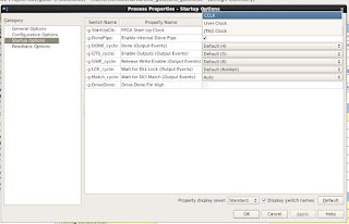
To use (program or flash) particular device, an option needs to be selected (under Startup section where the Programming File is generated). It has to be Clock Source as JTAG (for programming FPGA) or CCLK (for programming PROM)
See pictures: Right-click on 'Generating Programming file' brings pop-up menu, where 'Process Properties' has to be selected.

Then in pop-up window click on left hand side 'Startup Options' and select from three options next to 'FPGA Start-Up Clock'.
Select:
CCLK when flashing PROM memory
JTAG Clock when flashing FPGA (USB -> through JTAG)
Apply, OK.
After this double-click Generating Programming file to generate bitstream file .bit (and this file is used to program PROM/FPGA)

Code:
-------
library IEEE;
use IEEE.STD_LOGIC_1164.ALL;
entity and_gate is
Port ( SW0 : in STD_LOGIC;
SW1 : in STD_LOGIC;
LED : out STD_LOGIC);
end and_gate;
architecture Behavioral of and_gate is
begin
LED <= SW1 and SW0;
end Behavioral;
-------
This project needs another file, which ties SW0, SW1, LED abstracts with physical hardware. To do it, we need a Constraints file .ucf
It tells the builder where the connections go.
It looks like this:
------
NET "SW0" LOC = "N15" ;
NET "SW1" LOC = "J16" ;
NET "LED" LOC = "L14" ;
-------
I saw it working without last Loc in quotations marks, like below:
---
NET "SW0" LOC = N15 ;
NET "SW1" LOC = J16 ;
NET "LED" LOC = L14 ;
---
Unfortunately, this file not always gives errors when used, or defined incorrectly. When I forgot '=' between LOC and N15, nothing was told during project build, but nothing worked! So be sure to have it checked when debugging.
The names of pins are taken from Reference Manual (from DIGILENT website)
Below is a part of the schematic:

Switches, pushbuttons, LEDs and 7-segment displays
Here, connectivity of Nexys can be established, and this is where from I have N15, J16 for SW0, SW1 and L14 for LED.
Finally, check my video of how it works:

Comments
Post a Comment